The McRideline
If you are reading this as a sharpener then this will make sense. If you are reading this as a groomer then pay attention your lovely curved scissors are a pain to deal with.
Why are they a pain?
Any decent set of Semi bevel edge or fully convex scissors will have a hollow at the back. The cutting surfaces will be formed at the edge of this hollow with a flat at the back of the blade where the two blades of the scissors meet and ride over one another. We sharpeners call this the rideline as we have a total and utter lack of imagination.
For straight scissors this is really easy to repair as you simply get a flat stone and then hone the back of the blades on this and providing you aren’t 100% cack handed you will have a decent rideline.
For curved scissors this get alot tricker as no two scissors will have the same curve on them so it is utterly impractical to carry a stone for each and every curve we might encounter.
Various methods have been used to dealing with these from the simply running away, using a small square stone and judging it by hand, popping outside and rubbing it on a pavement kerb, using round stones and still judging it by hand, drain pipes and sticky back sandpaper.
The problem with all of these methods is it relied upon you keeping the scissor blade well aligned which is somehat difficult to keep the angles correct.
Then a few years ago a sharpener in the USA called Jim cooper came up with the precise ride which was a laser cut and 3D printed jig that solved all problems with holding the scissor at the right angle.
I saw this at Ryans Northumbrian sharpening where my inner tight git made a deal with my engineering mind and said “I can make that!!!”. That thought then got filed into the back of my mind while getting barras blades up and running was my main task.
In the meantime I purchased some cheap curved stones from a UK supplier which with a wee bit of bodgery worked if balanced ontop of the russian machine.
Then I saw another machine over in the USA
This machine is fully 3D printed and was closer to what I had in mind. I have not seen this machine in person but I thought I could take the best of the two USA machines and combine them into my own design. As well as convertng them over to a measurement system not based on the length of a long dead kings right foot.
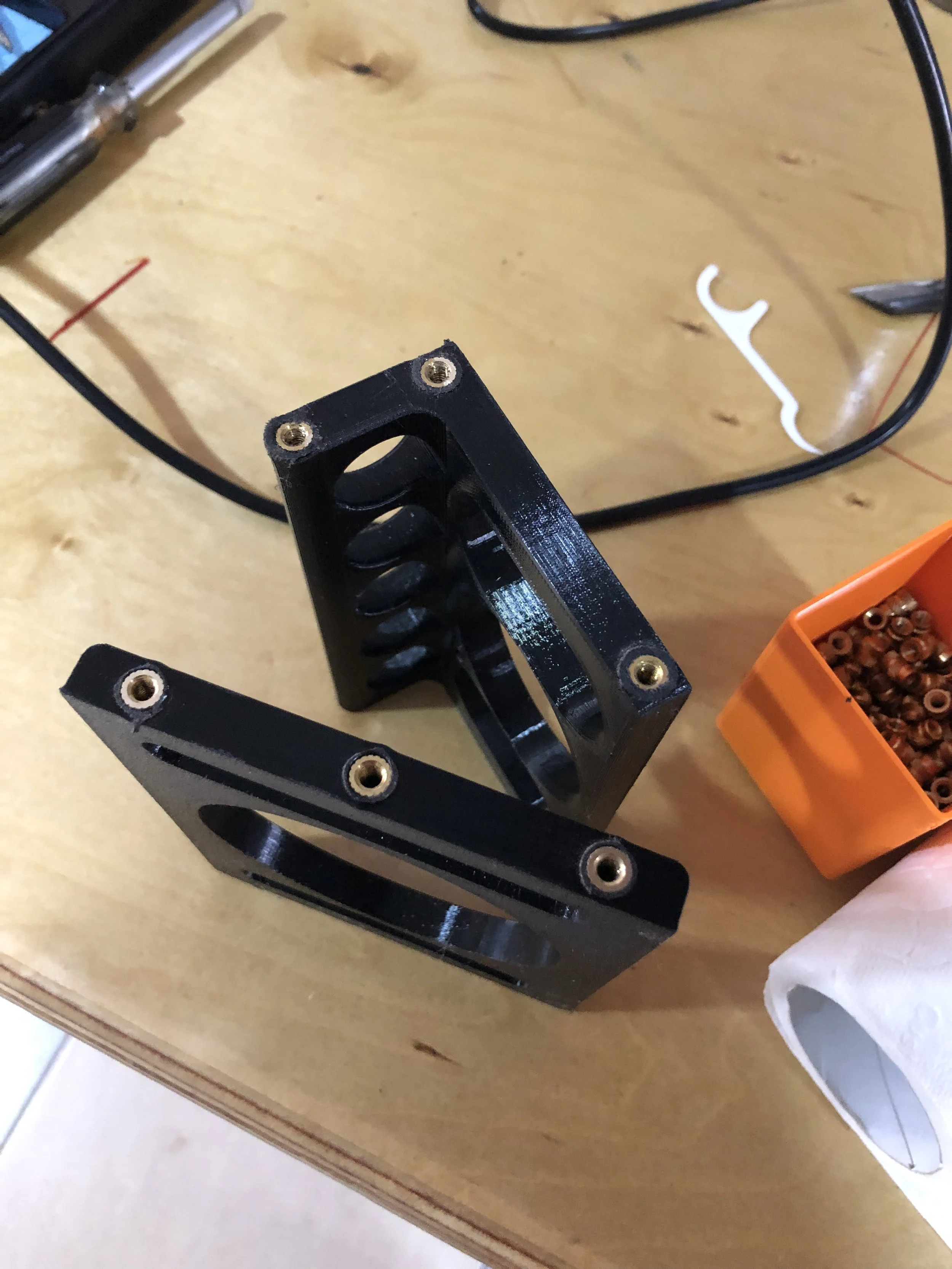
With a rough sketch in my head I knocked up a design using the stones I had as well as some spares from the 3D printer and some nuts and bolts I had hanging around.
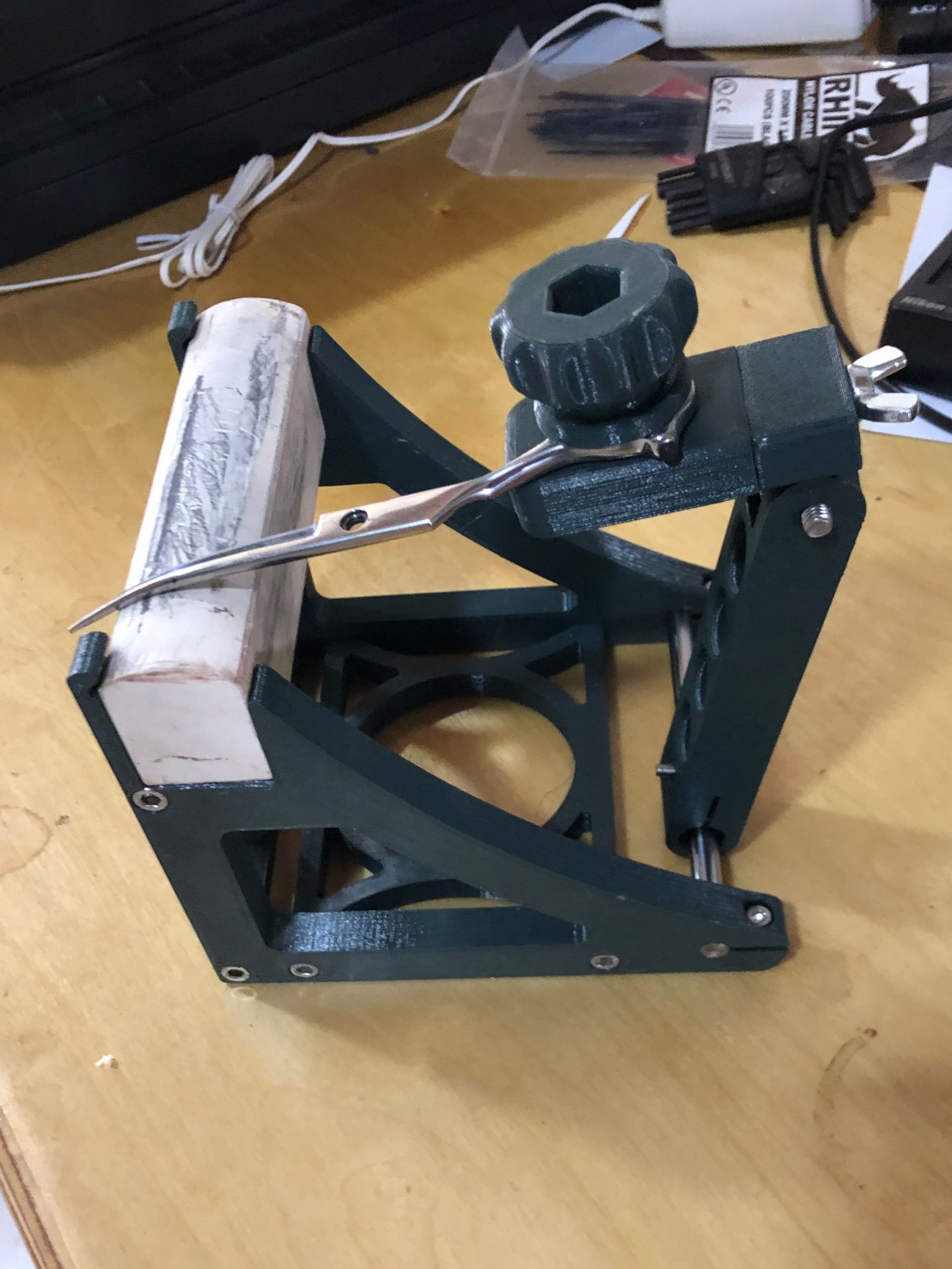
This is when the McRideline Mark one was spat into creation.
I posted this up in a top secret sharpeners forum where I got a reaction similar to a bunch of nerds hearing of a new Marvel movie.
To get some feedback on how to improve the machine I made myself another one and chucked the first one over to a sharpener (Dave of Simply Sharp) who uses the Precise Ride as well as sending the files to another sharpener who had a 3D printer in the toy box.
This brought back some feedback
The UK sourced stones are soft as $^$%
The one piece arm is a bit restrictive
The stones was no great surprise so I had a plan B in the works already which used a 3D print the same shape as the stones but with a clamp for sandpaper
The two piece arm was something I was a bit more dubious about but Dave was pretty insistant so after getting a bit of a beefier bearing I designed one and don’t tell him but I prefer it to the one piece arm.
I was also slightly dubious about the merits of simply threading the 3D prints so I gave heat set inserts a try
After good bit of redesigning the Mark 2 came into being which shares just the scissor clamp with the Mark 1
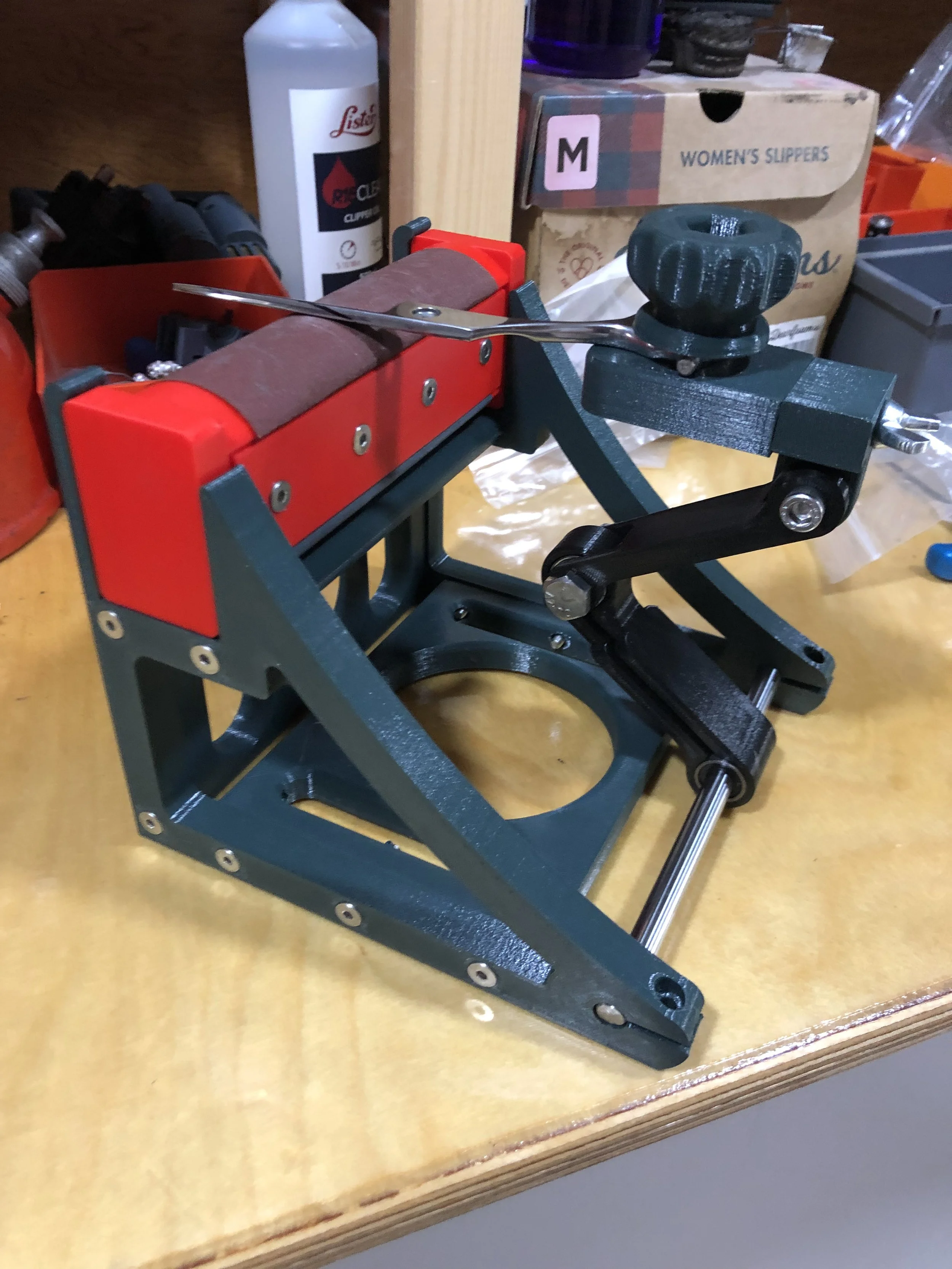
That takes us to late June 2022
There is evidently a demand for the McRideline.
But before I put down the deposit down on a Ferrari Caterham 7 620 it’s time for my morals to get in the way.
The printer I use the Prusa i3 is an open source project where anyone can download the entire design and make their own. I like this way of doing things as the community can improve the design and this has already happened with the McRideline with input from other sharpeners.
So I’m going to make this an open source project.
This means that the design files will be freely available for anyone to download as well as the full BOM (Bill Of Materials) which means you can print your own. You can even convert it over to a measurement system based on a dead kings right foot.
I am however well aware that most won’t have a 3D printer so I am also going to be selling the McRideline via this website. Initially to the UK only until I have worked out the wrinkles in shipping etc. I am happy to do deals with those that want to sell it onwards via there own established networks but I want to keep control over this and to stay in touch with customers.
I also know that finding the parts is a pain in the hoop so I will also be selling a kit of all the metal parts that will let you print your own parts and then assemble it yourself.
A user group has been created on facebook if you want to ask questions, request features, get assistance in printing, get assistance in using etc and so on.
If you have stumbled across this page before I stick it out to the world then watch this space I still got a good few things to work out
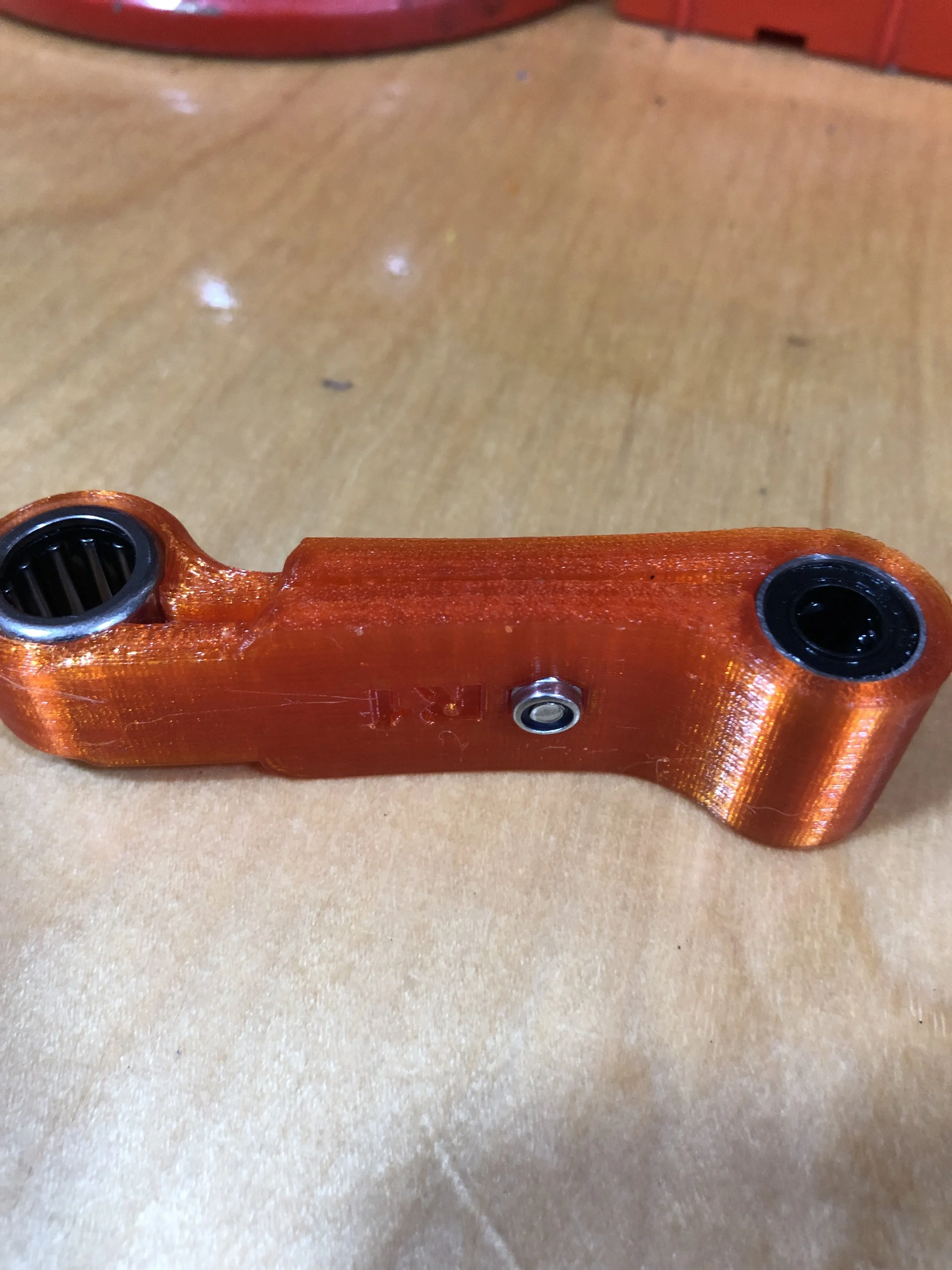
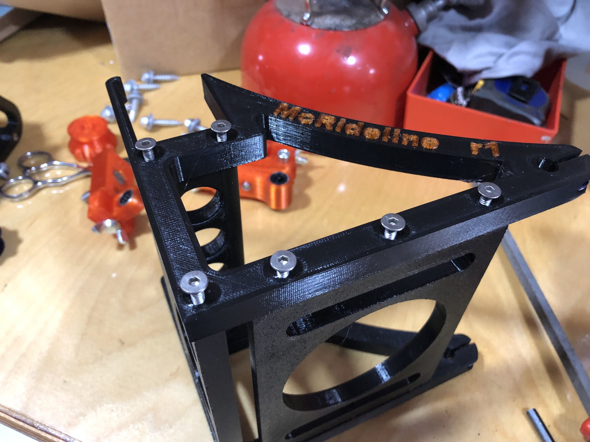
The parts
To make communication easier lets see what I call each part of the machine.
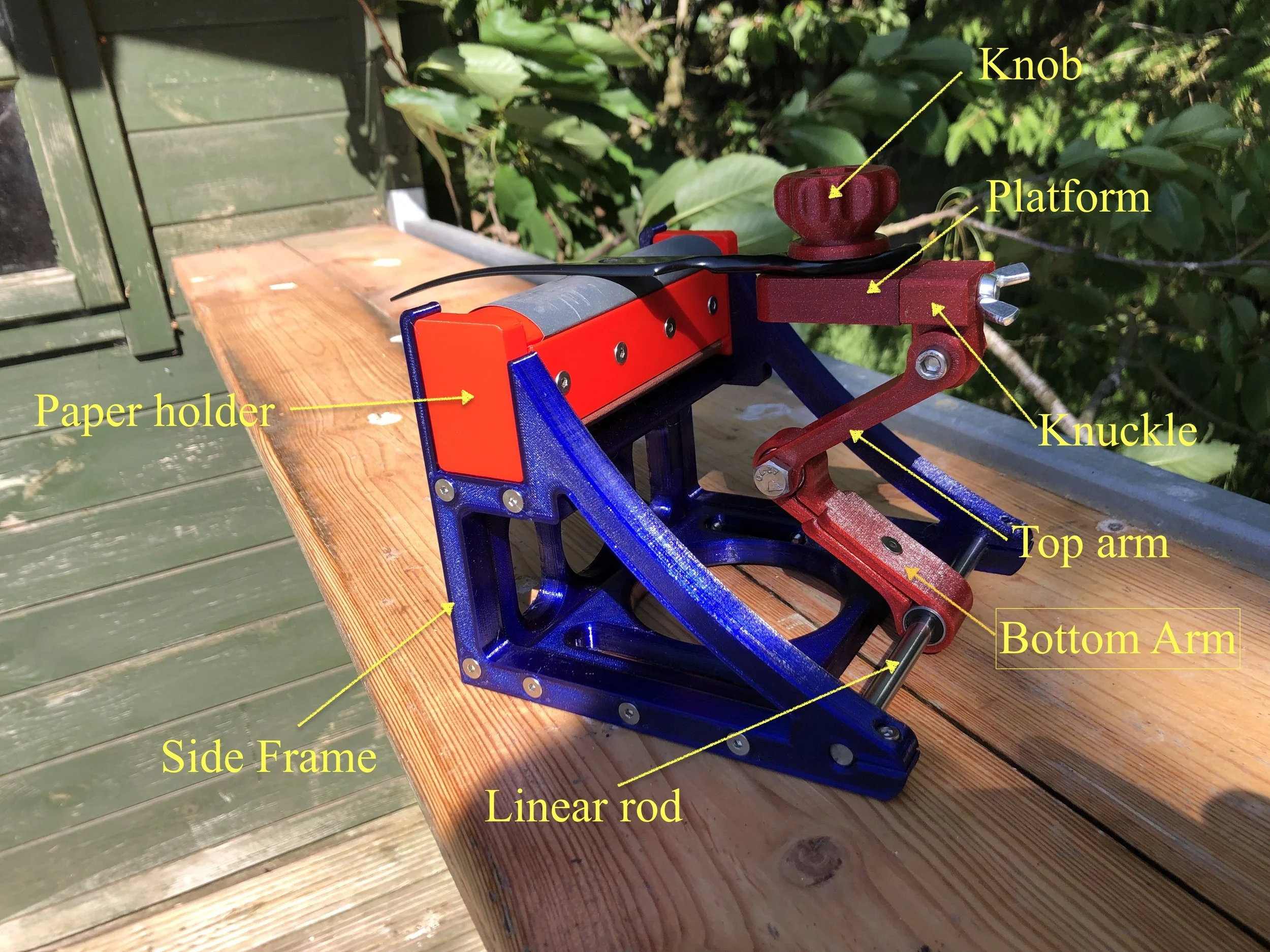
I haven’t labeled the back or the bottom, but i’m sure you can work those bits out.
The Files
The files for the machine are hosted on Printables.com
They will be open source but not for commercial use. So no moving to China and making a million of them but you are perfectly welcome to make one for your own business.
Also you are making it at your own risk if you manage to chop your arm off then that’s your problem.
The bill of materials which is a list of parts which you need to purchase is HERE
If you are a wee bit on the lazy side then there is a pre-made kit for sale HERE in my site shop
Printing tips
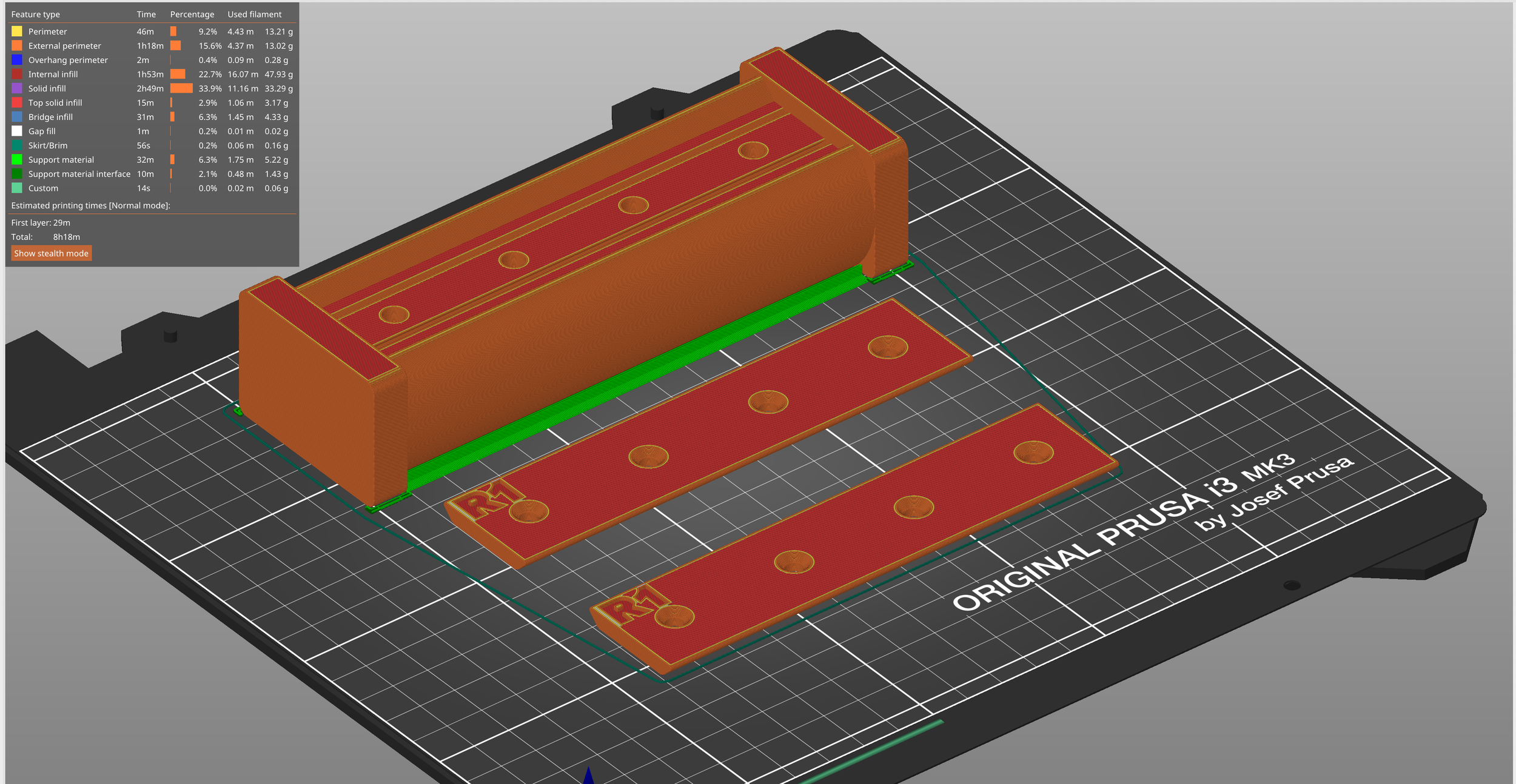
3D printing assuming you are using an FDM machine produces a final product which has a grain like wood so it is far stronger in some directions then it is in others
I’m no expert in 3D printing but this is how I am printing it
I am printing the structural parts of the machine in PETG as I like it. I find it is a bit more flexable than PLA which is the most common 3D printing material. If you want to experiment with ABS, Nylon etc then go for it. Once i have most of the bug ironed out i’ll be printing it out in Prusament PC-CF
For a 3D print most of the strength comes from the outer shell of the part, not from the infill. I have left infill at 15% but i have put the permitters up to 4 or 5 depending on the part.
Most parts are designed to be printed without supports as much as possible.
The exceptions to this are parts of the arm.

The knuckle
You CAN print it this way quite easily but the downside of this is the layer lines are at 90º to any hoop stress in the bearing mount ring.
This creates weakness and i have had a good few failures in use and when mounting bearings
Don’t do this

The knuckle a better way
If you have some experience in 3D printing this way will seem like a mistake.
But printing it like this puts the layer lines in parallel with the hoop stress of the bearing mount ring which gives you alot more strength.
So DO this

Arm pieces
These can’t be printed without support material. The bottom of the arm should have support materials on build plate only as if you select everywhere then you get support material in the nut cavity which will be hard to remove.
The top arm you have to select build material everywhere. The support material isn’t too hard to remove and a quick sand on the inner faces and you are ready to go.
Paper holders
These can be printed in PLA
I find the orientation shown above with supports is the best way to print the central part.
Assembly
If you purchase a machine from me it will come fully built and ready to go. this guide is either for whe you roll your own or you want to fit new parts.
The assembly is pretty easy so I shall be brief. I will add in sections as the community finds stumbling blocks.
The one thing that will probably be new to you is the heat set inserts which sound intimdating but that are really quite easy
Have a look at CNC Kitchen for more details. If you can afford it then get the proper tools from CNC kitchen for inserting these
Tools needed
6.5mm drill
small adjustable spanner
metric allen keys
sharp knife
De-burring tool (if you are into 3D printing buy one of these)
Small file
Soldering iron
Water pump pliers
Support removal
Some of the parts need to be printed with supports enabled and these need to be removed. You will also need to clean up and elephants foot etc. This is when the sharp knife, deburr tool and the file are useful
Arm assembly
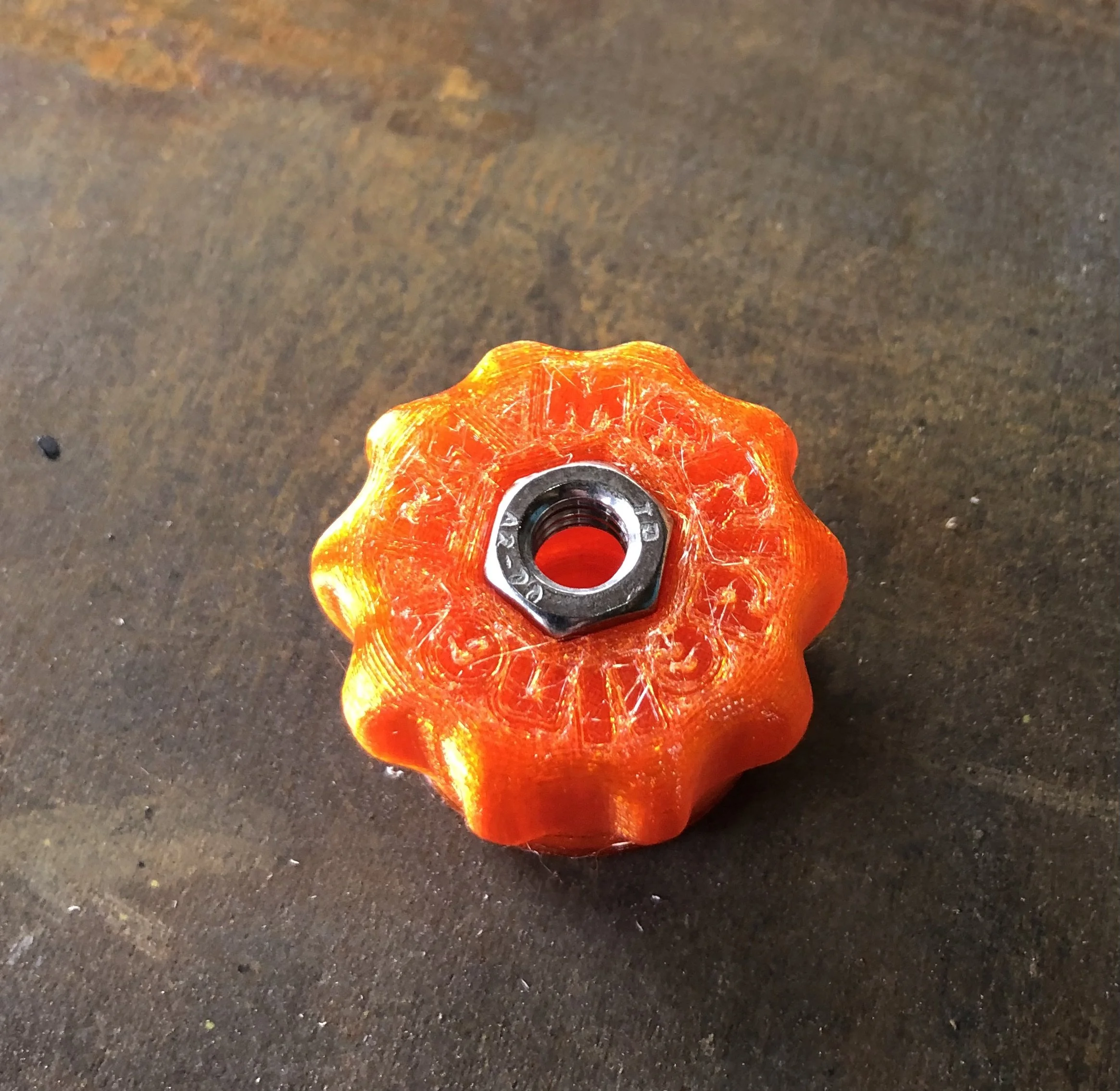
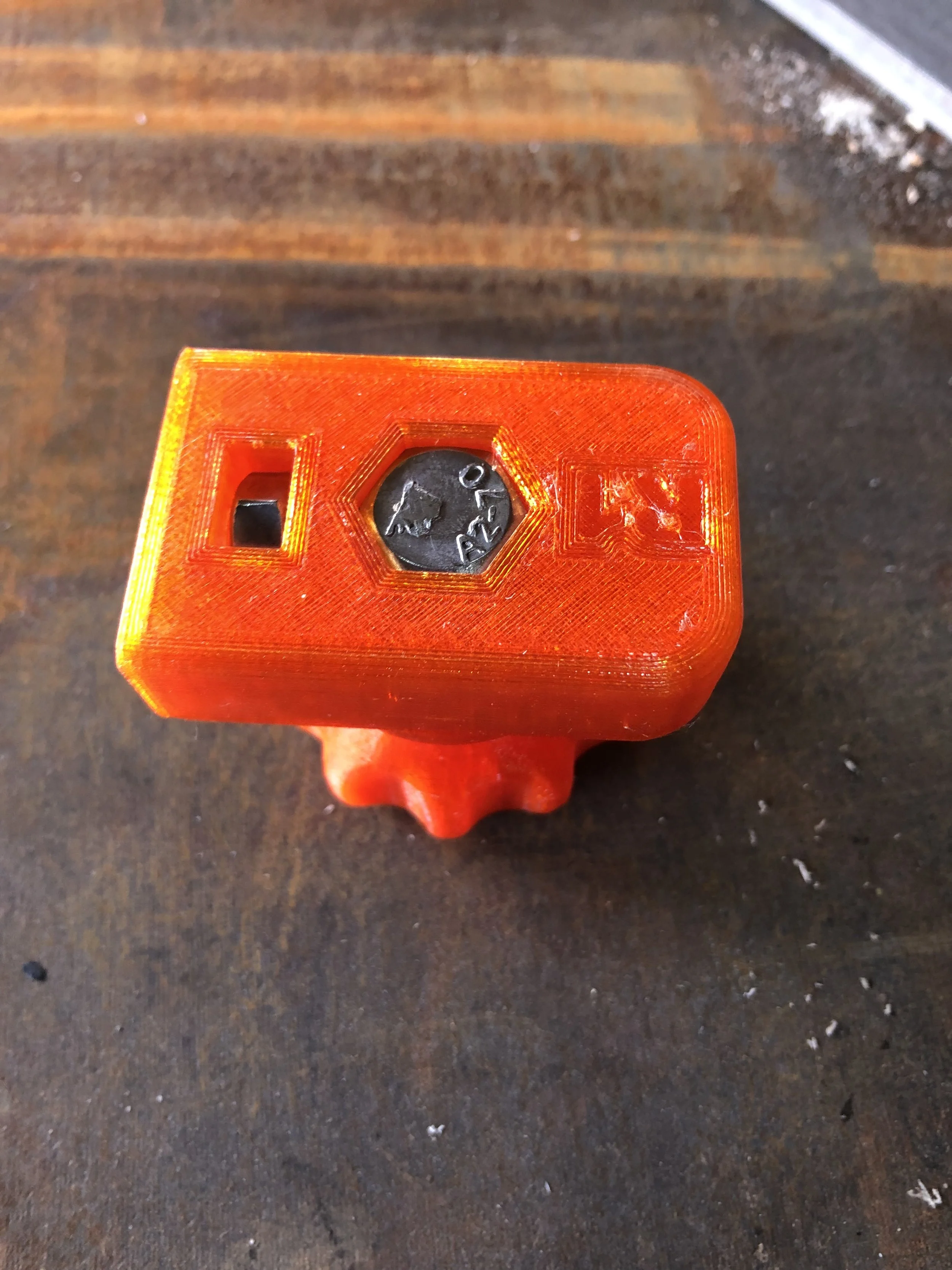
Knob
Take one M8 nut and push it into the hex hole. if it is a wee bit on the lose side then a dab of glue or use a soldering iron to rough up one wall so it is retained into the knob
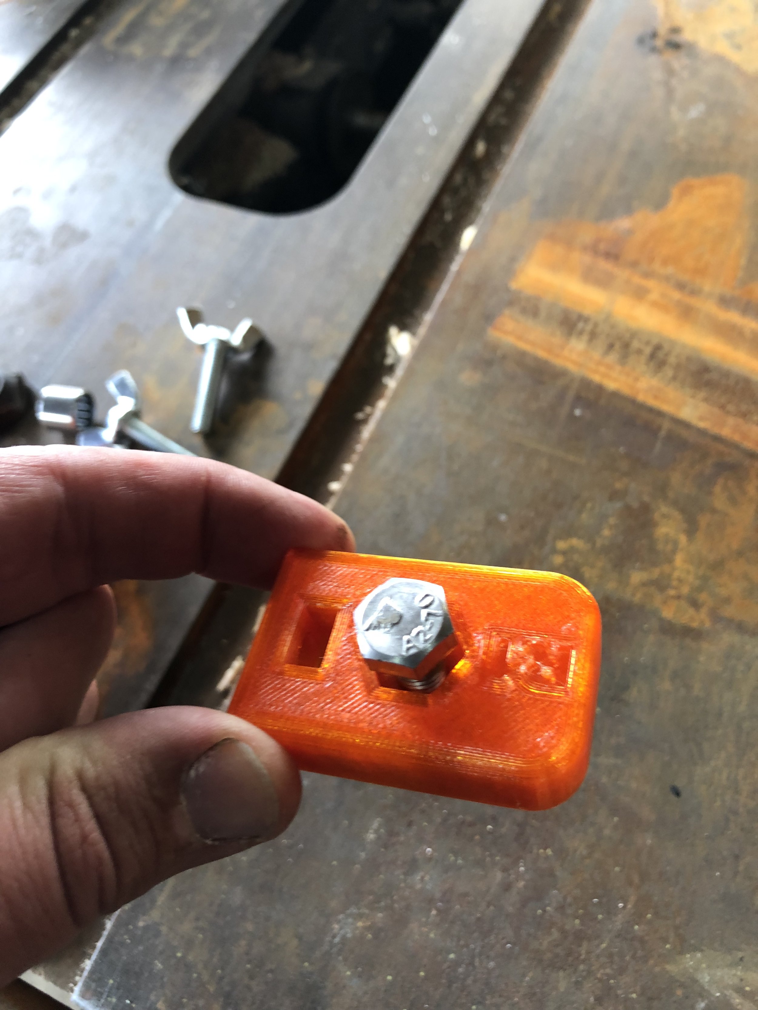
Platform
Wind in the M8 bolt or push it through if you can until it is almost all the way in and it is aligned with the hex.
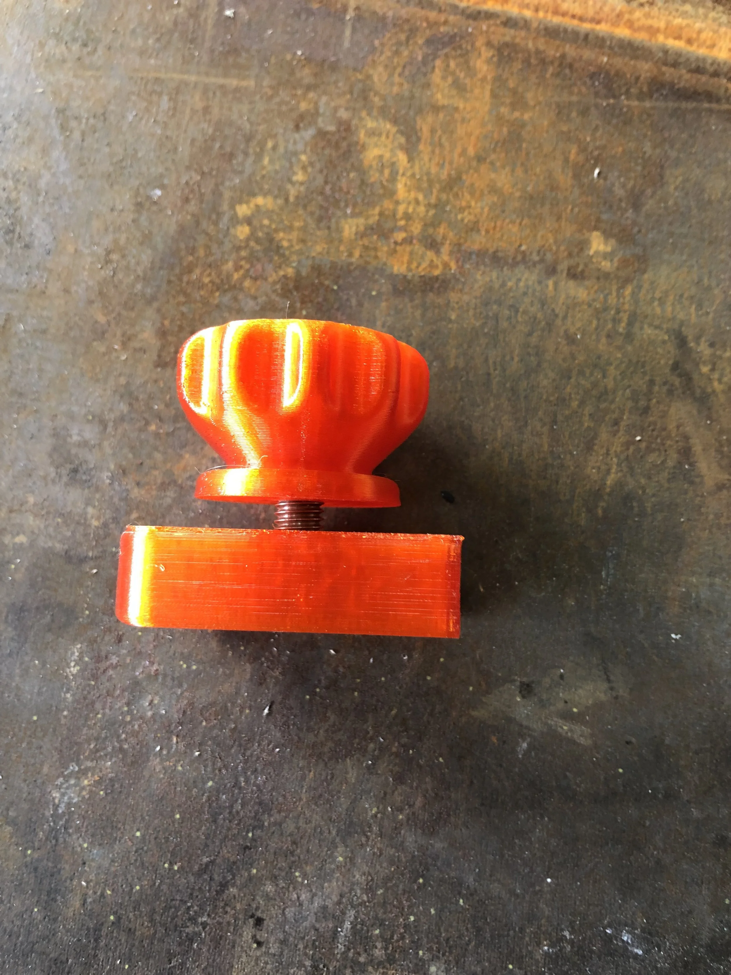
Platform
Using the knob pull the bolt in fully home
Platform
Drop in the M6 nut into the platform.
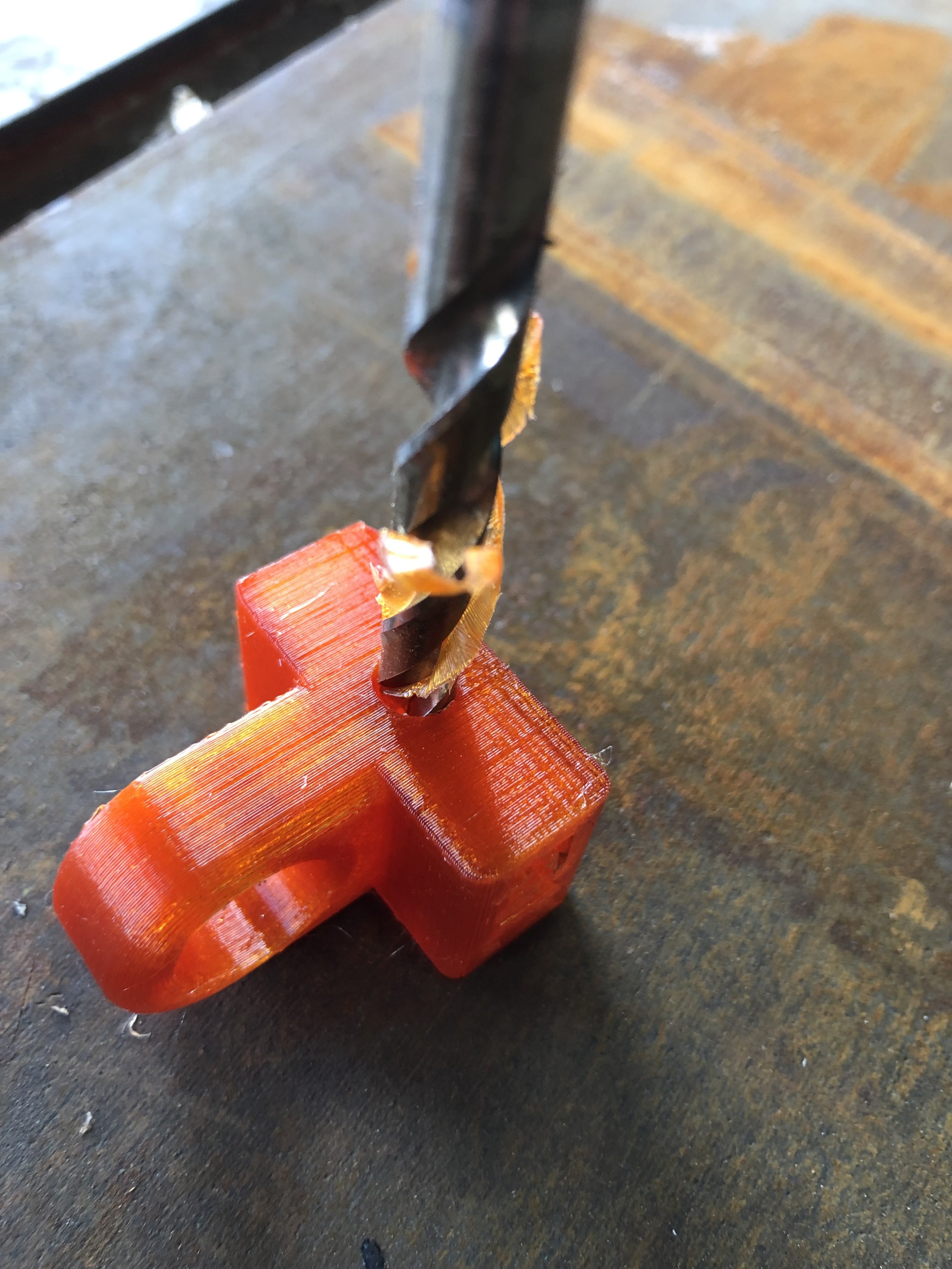
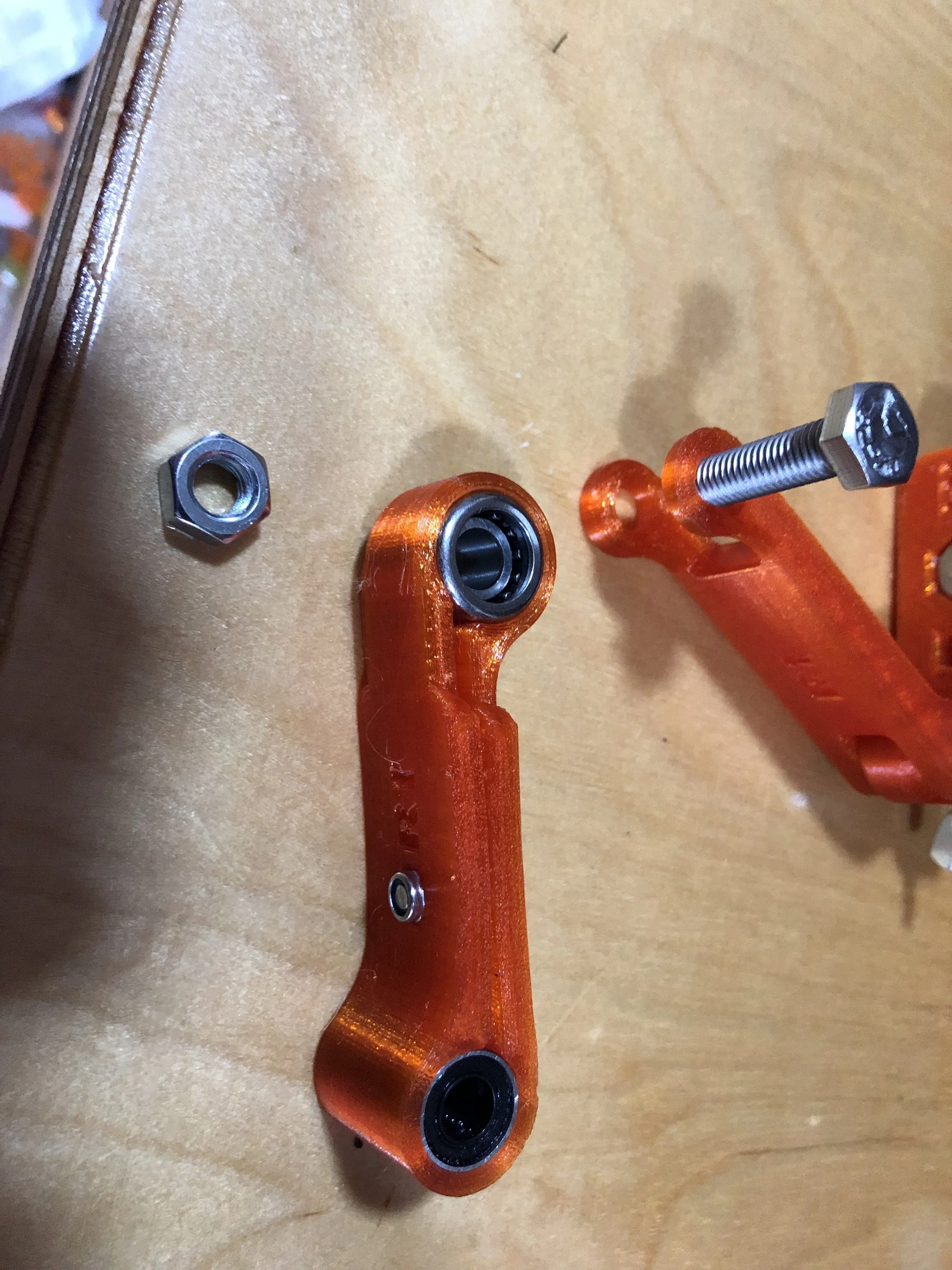
Knuckle
Take the 6.5mm drill and drill the through hole out to 6.5mm so you have a bit of clearance
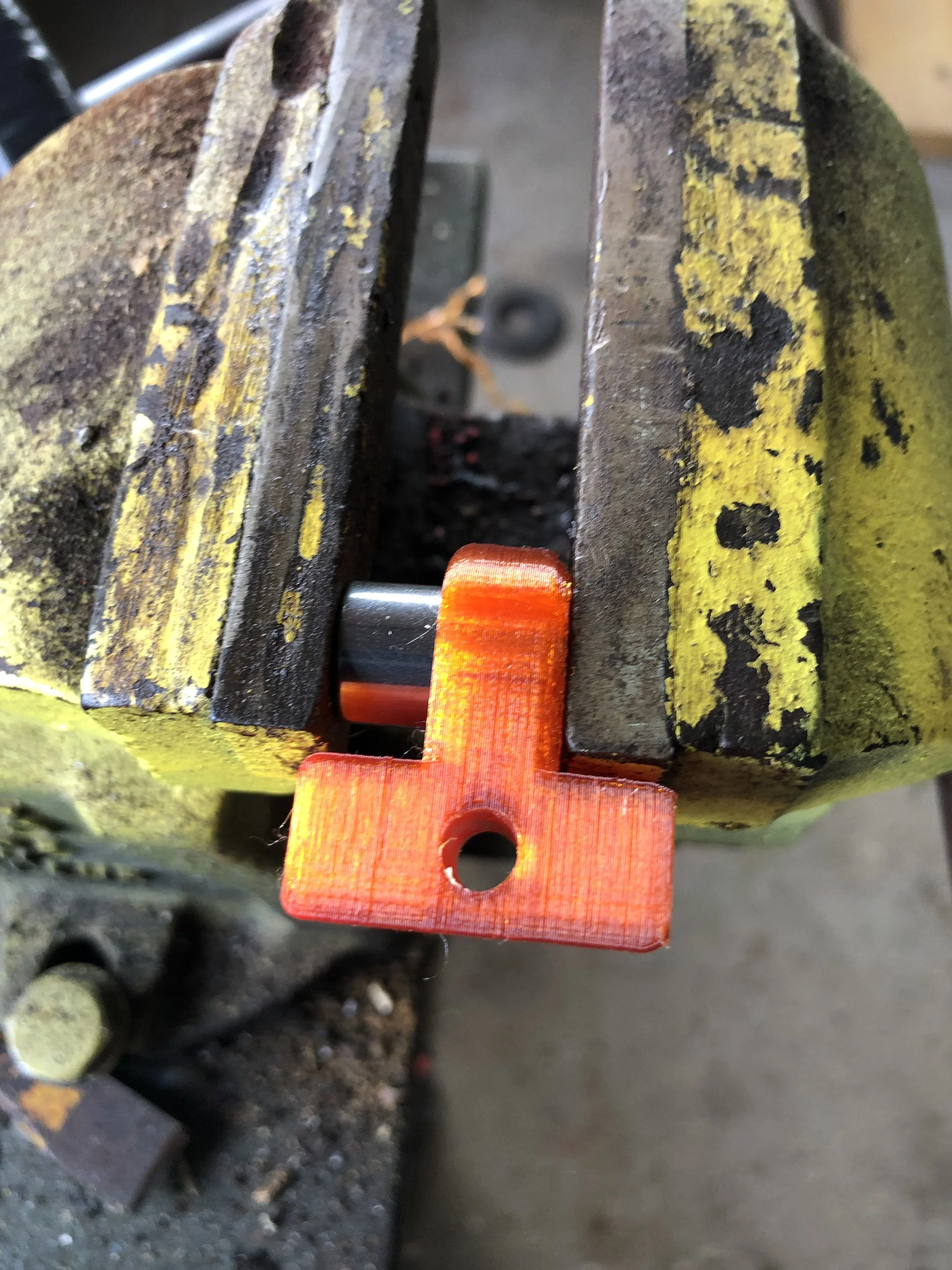
Knuckle
Using a vice or something else push the bearing outer into the knuckle
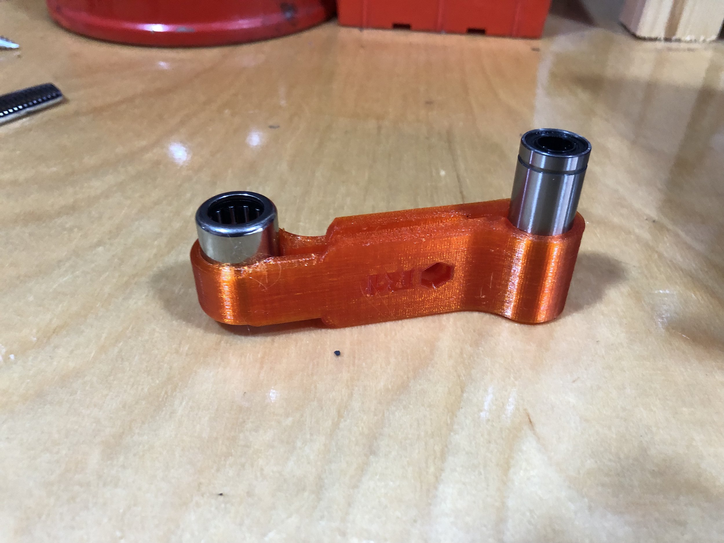
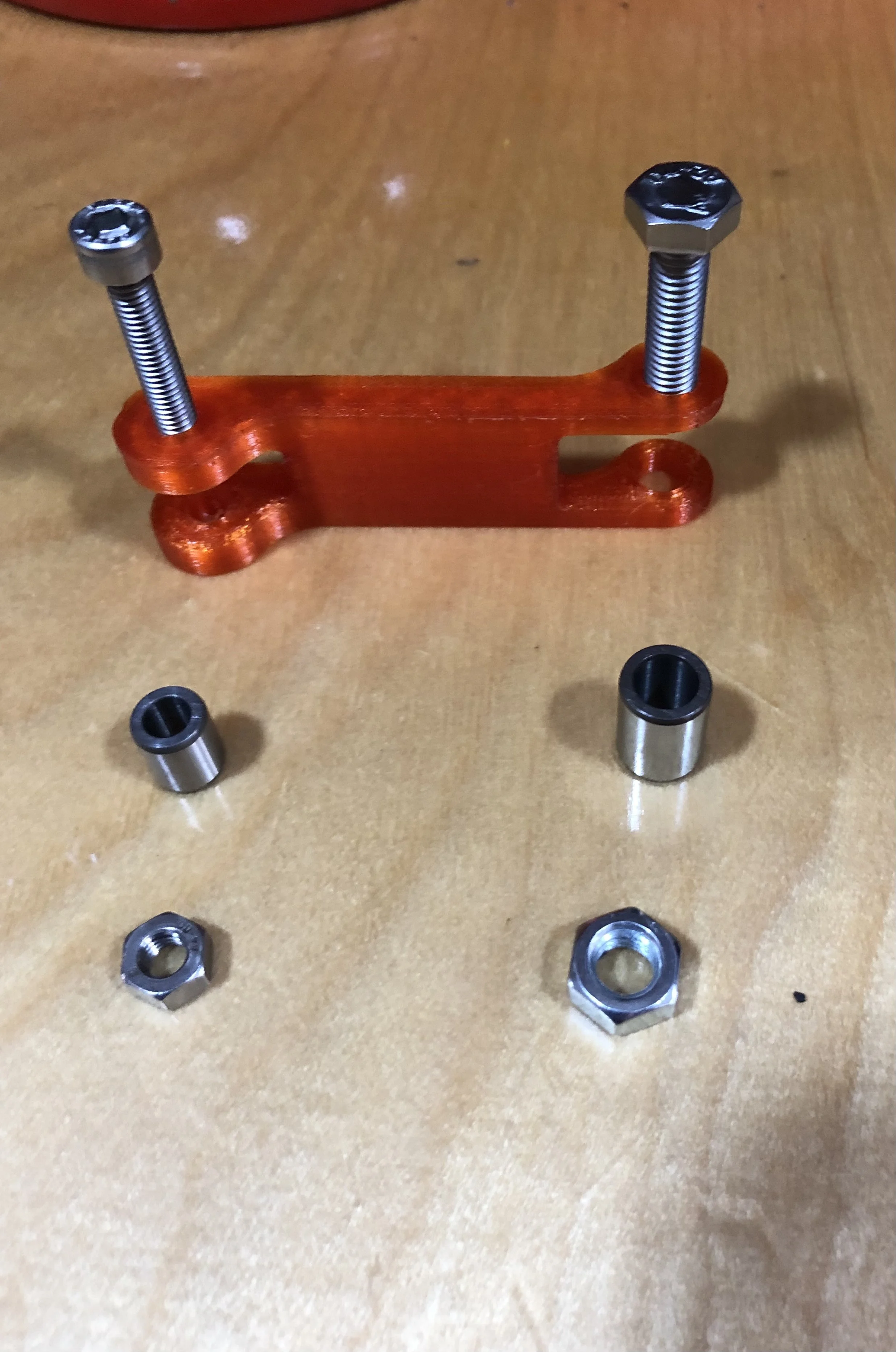
Arm bottom link
Press in the two different bearings. These should need nothing more then finger pressure
Bottom arm link
Using an M4 x 12mm counter sunk and an M4 nut pull the two sides of the arm together. This can be left our but you will experience more twist in the arm.
Top arm link
Pull together the bolts and bearing inners from the BOM
Arm top
Assemble the knuckle and platform together and insert the bearing inner
Top bolt
Line it all up and put in the top bolt. How tight you make it is purely down to preference. I leave mine quite slack, you can even run without a nut if you want. the tighter it is the less slop you have but the tighter the pivot is.
Pay attention to the offset so the arm folds up nicely
Mid bearing
Same as above insert the bearing inner and assemble and tweak the tightness to get the joint you want.
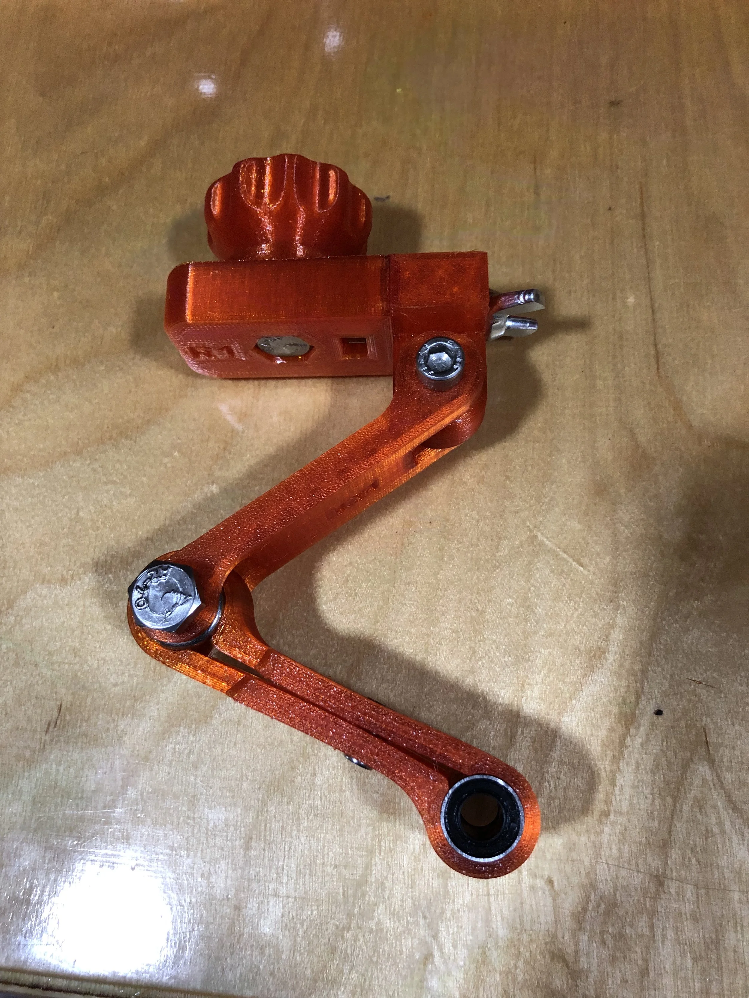
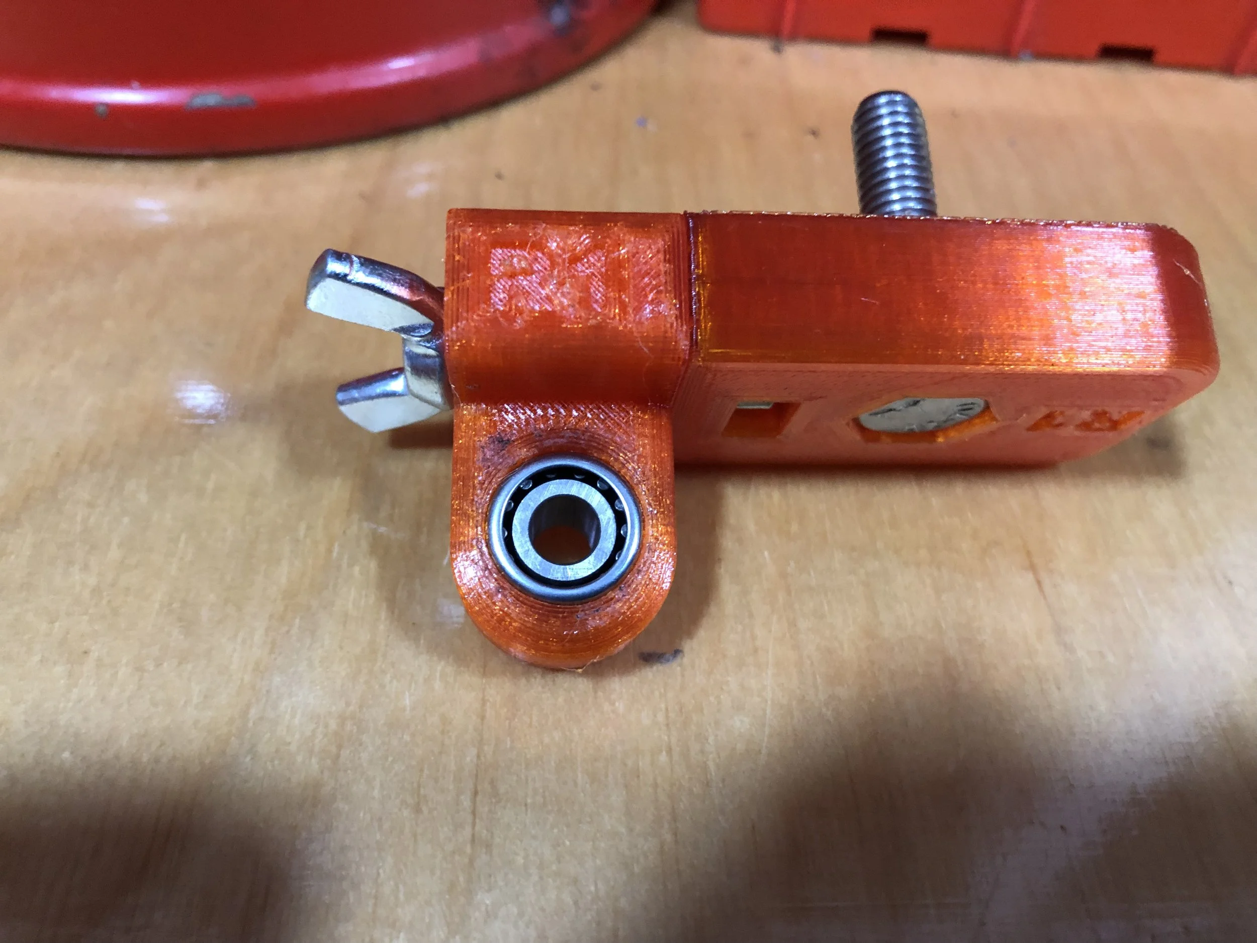
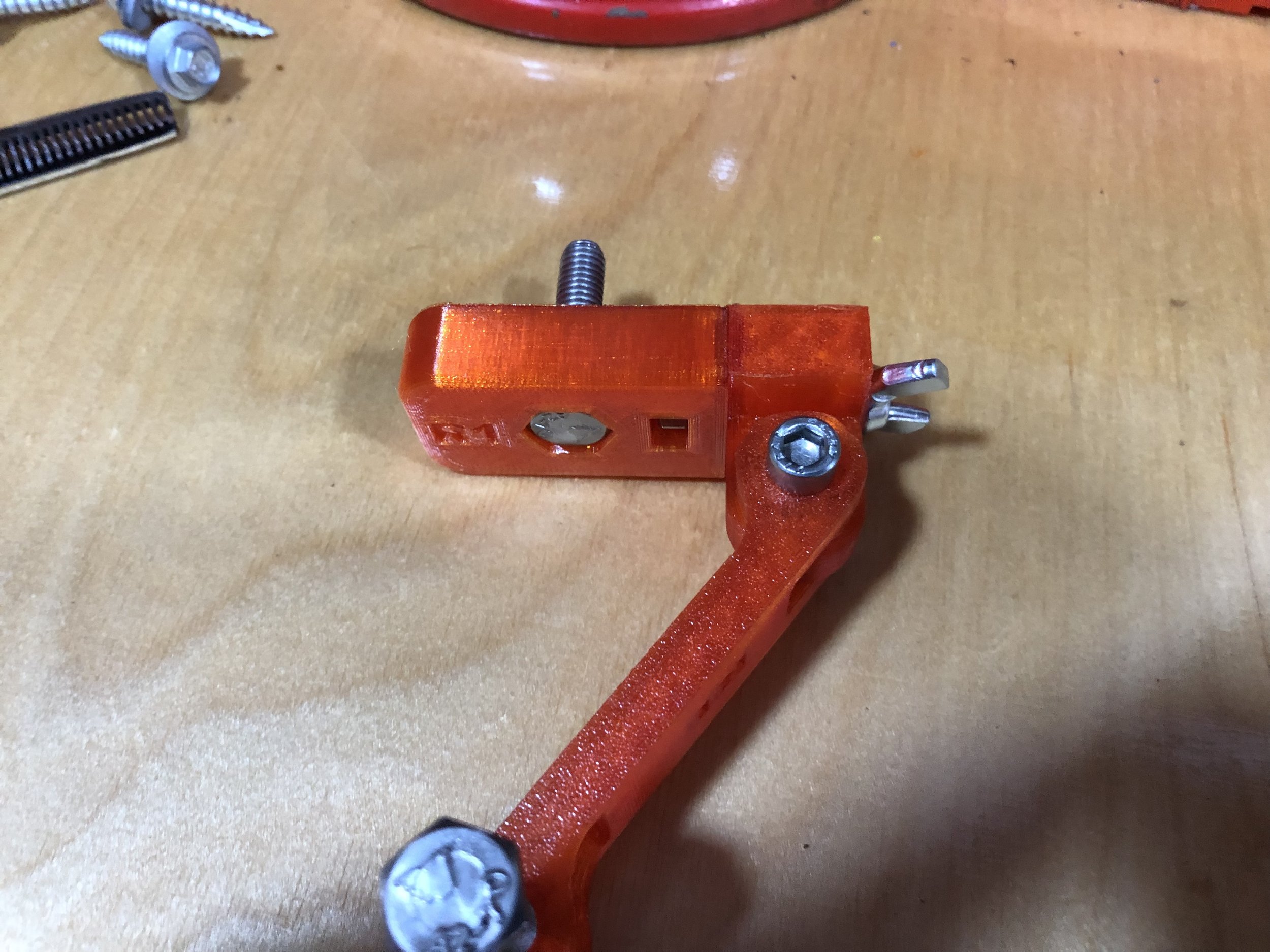
Finished arm
this is what you should end up with
Frame assembly
Same as the arm parts a quick deburr just now can save you hassle further down the road.
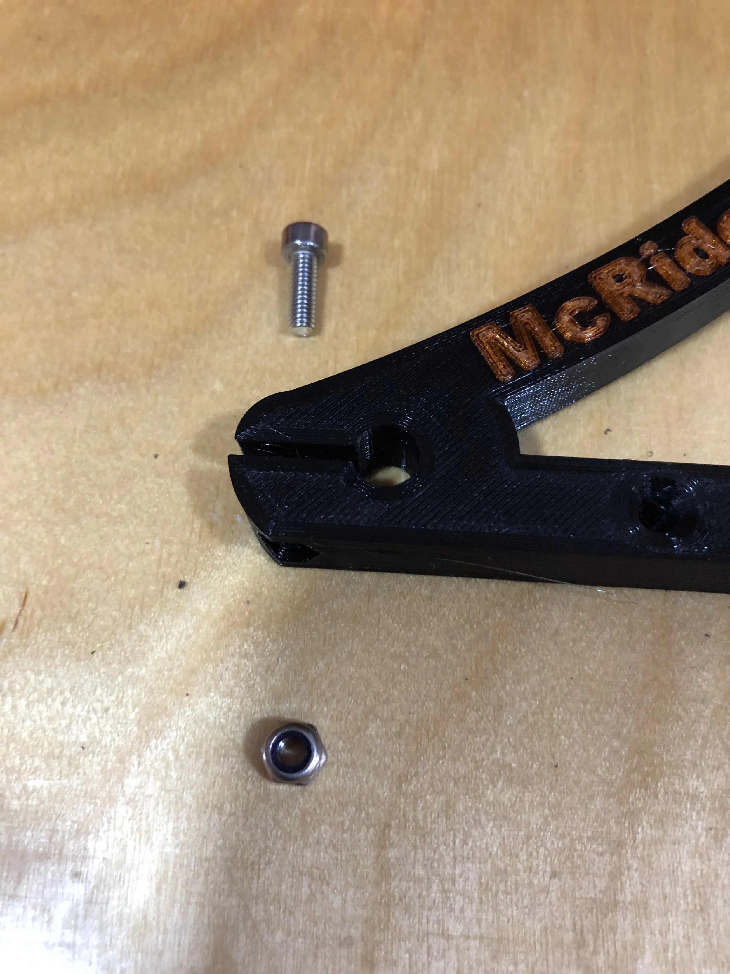
Frame pinch bolts
One of the tricker jobs is pushing in the nuts on the bottom. I normally use a pair of water pump pliers to press the nuts in.
This uses the M4 x 20 socket head screws. The nut can be a locking or ordinary nut
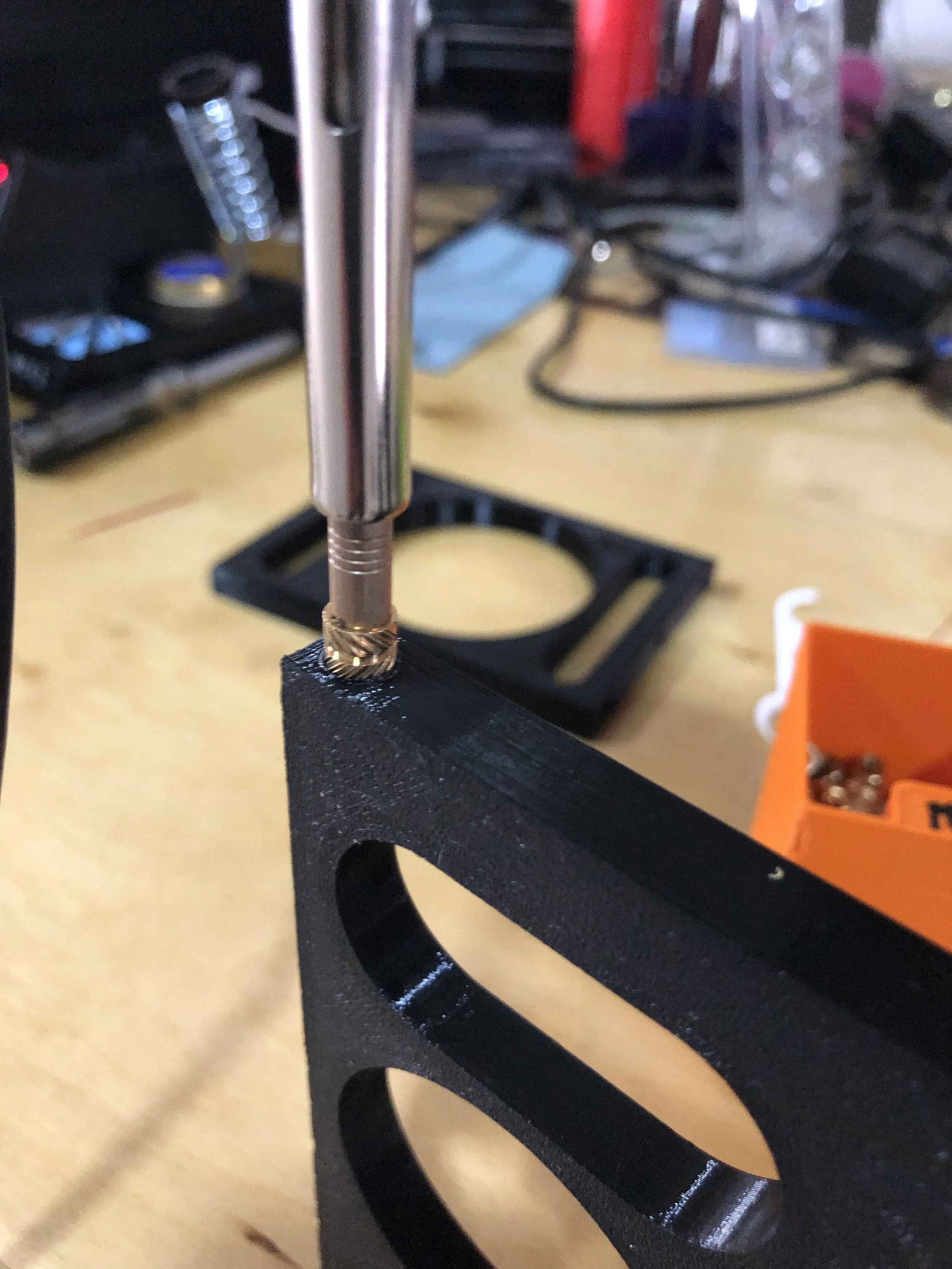
heat set inserts
Using a soldering iron insert the heat set inserts
heat inserts done
After you have got the heat set inserts in place you can give up the ends a clean up with a file so that everything sit together more nicely
Frame assembly
Bolt the four parts together. I’d get all the bolts in before you finally tighten a side
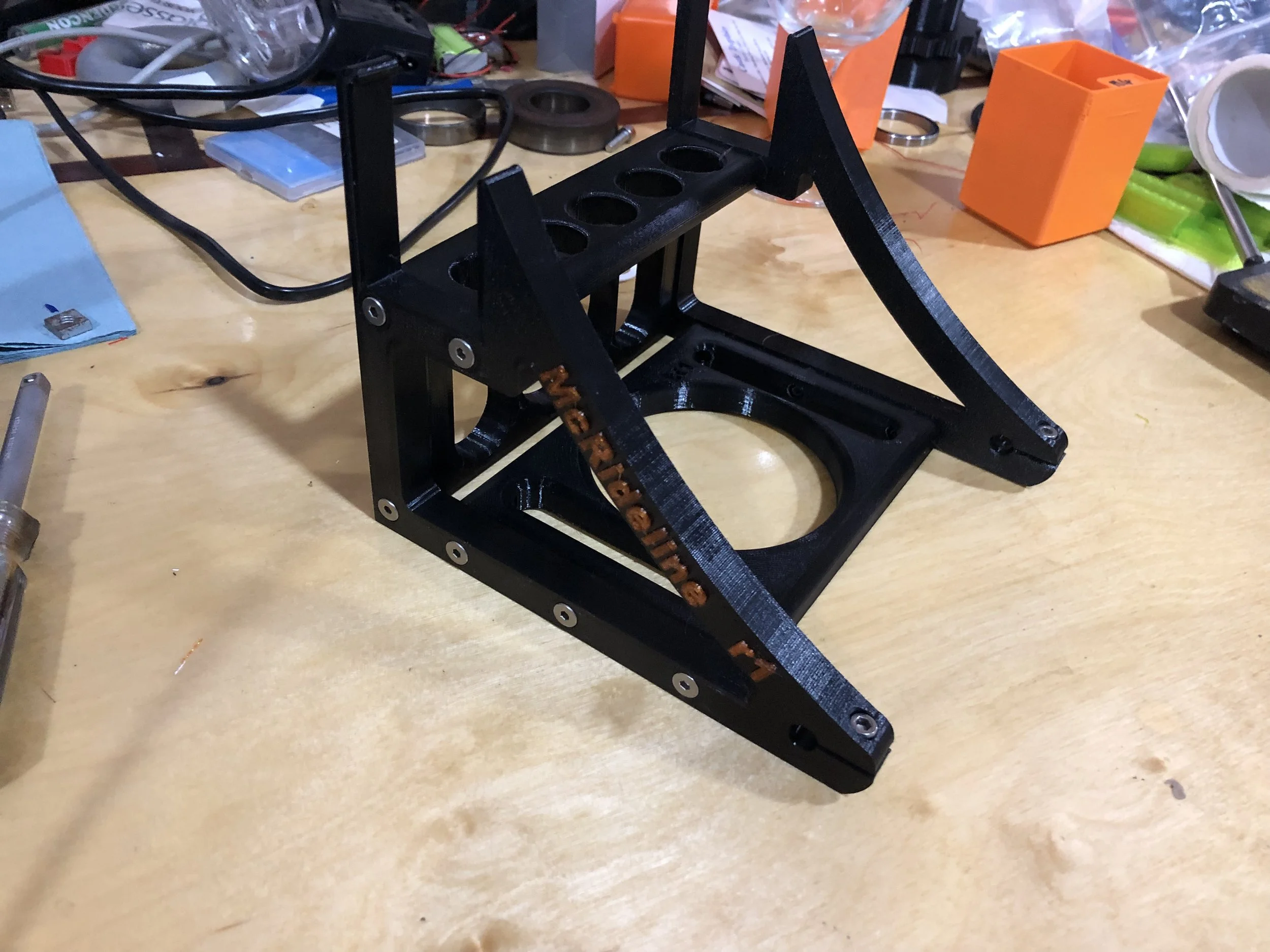
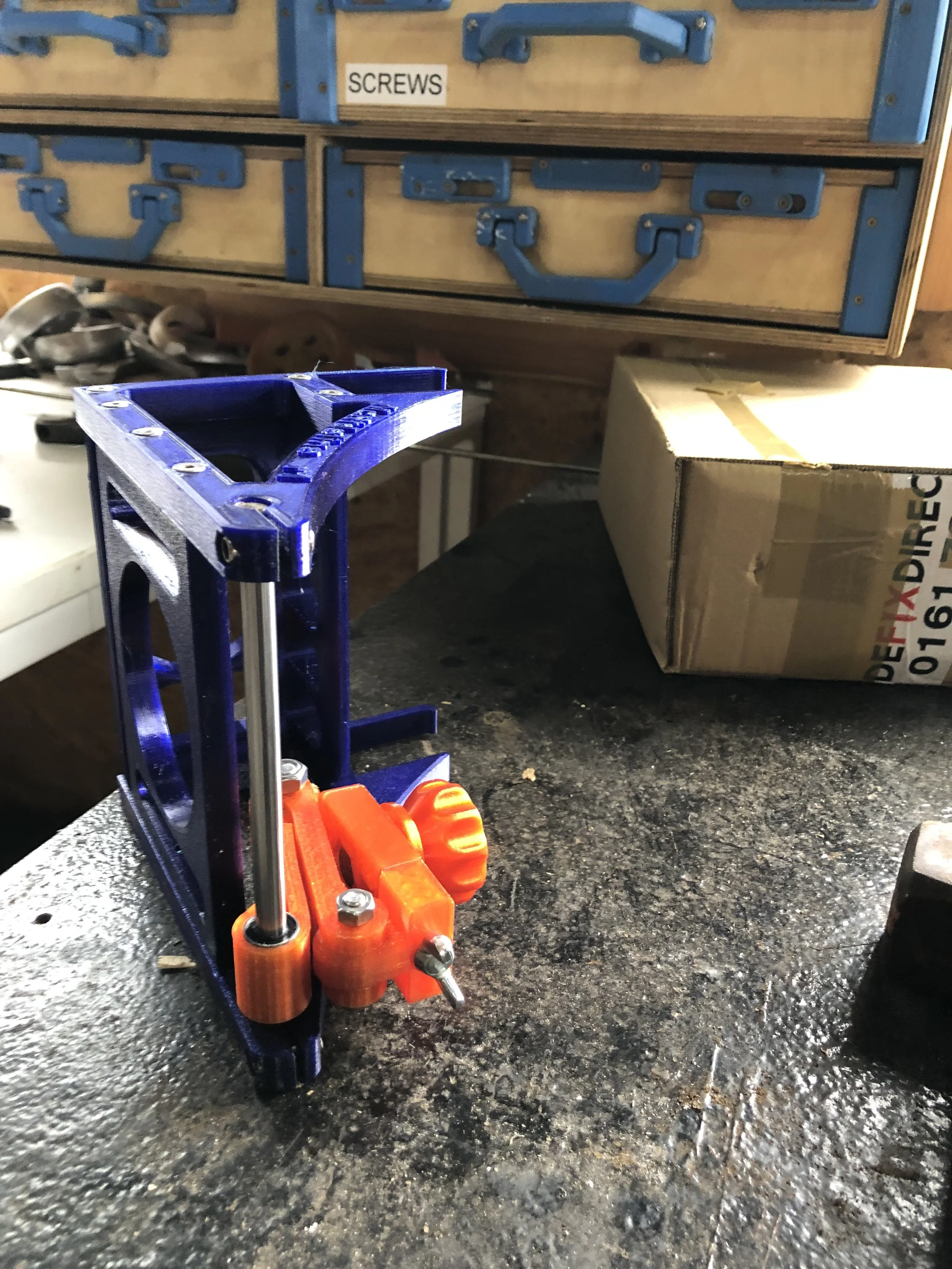
Finished frame
That is the fame assembled. You want to leave the pinch bolts lose for fitting the rod.
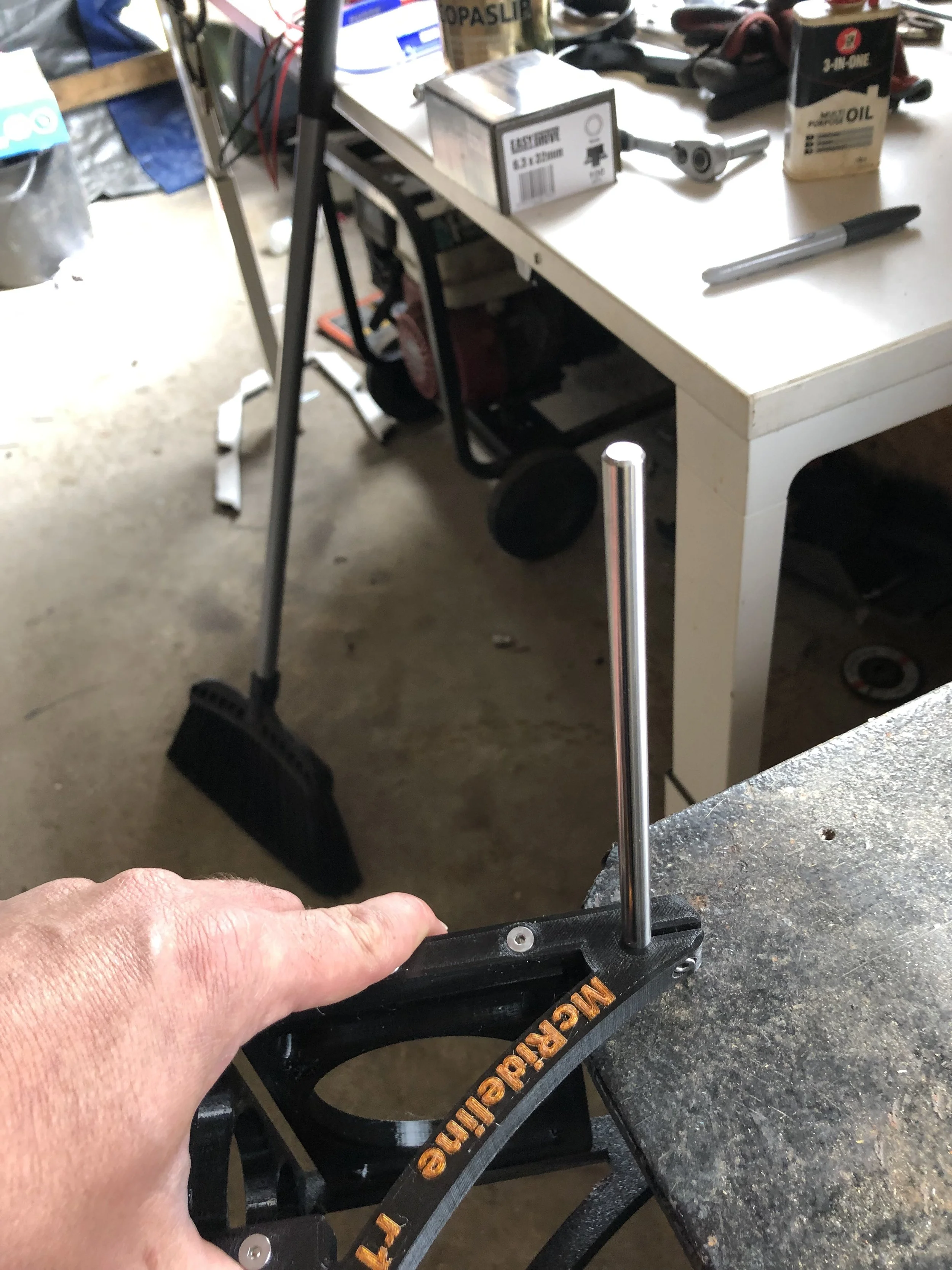
Rail fitting
Supporting the back of the frame gently tap the rail into the hole
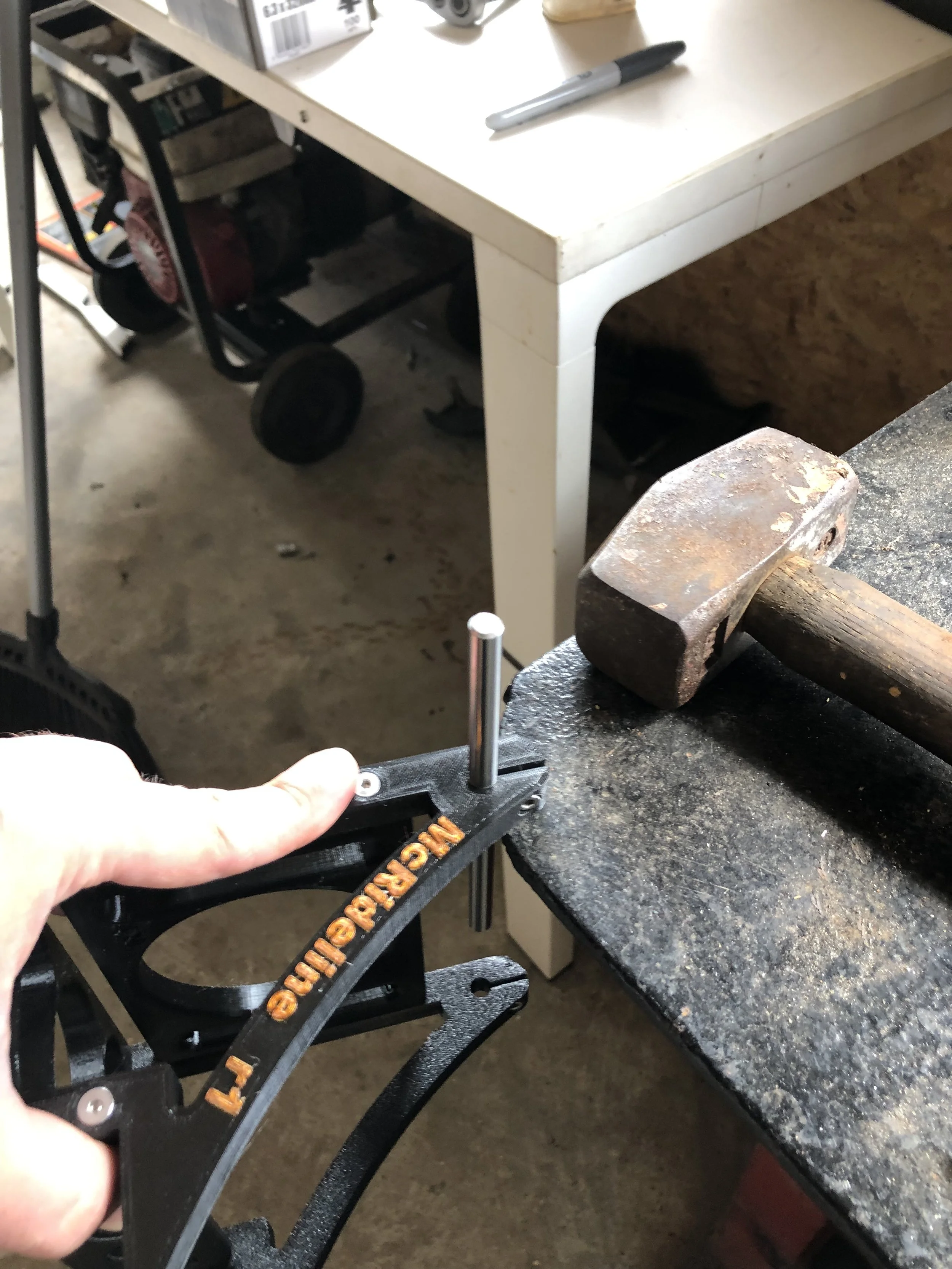
Driving the rail further in
Moving the frame further out on the table drive the rail further home but don’t hit it too hard as it might change colour. Also leave enough room to get the arm onto the rail.
Linear rail final fit
After putting the arm onto the linear rail. Support the bottom frame and carefully drive the rail into the far frame